The project
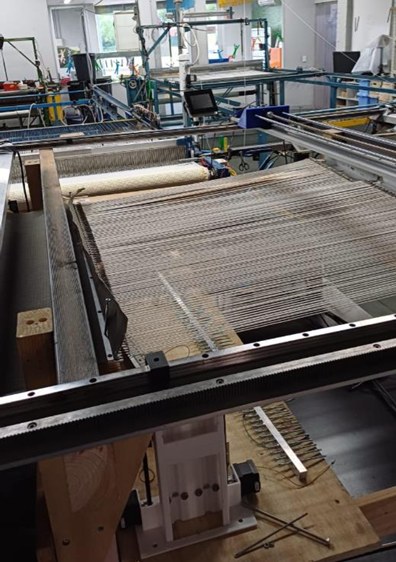
Mr Trampoline, a trampoline maker in Carnegie, Victoria, weaves its mats on machines that still need an operator to hook and tension every warp yarn. Together with RMIT, the company has been building a fully automated prototype that makes a 1 m by 1 m mat, and student groups have been adding to it for three years. My research covered the warp tension control section.
The prototype's warp beam was fixed to the frame. An earlier moving-beam design had failed because the gear and rack were modelled badly, so the beams could not slide freely. Tension is controlled from the moving beams, so that mechanism came first. This phase delivered the mechanical base. Closed-loop tension control is the next stage.
My part
In Part 1 I ran the FMEA, which ranked yarn breakage as the biggest risk and brought its score down from 240 to 98, and I redesigned the beams in SolidWorks. In Part 2 I fixed the CAD mating, fabricated the beam platforms, rails and gear mounting, got the gears meshing smoothly, chose rack and pinion over three other drive options, and ran the movement and repeatability tests. I assisted with calibrating the strain gauges against a digital scale, the roller tension test, and the wiring and Arduino code.
Part 1: measuring tension
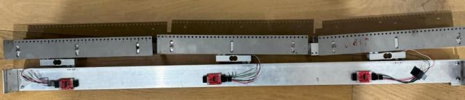
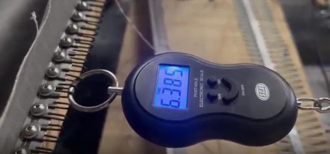
The first semester carried on the previous group's work on tension sensing. The warp is split into three sections, and a strain gauge on each section reads its tension through an Arduino. The three gauges were calibrated against a digital scale, and tension was then changed by pulling the mat with the roller motor while all three readings were logged. I assisted with both.
On my own, I ran an FMEA that identified yarn breakage as the biggest risk, with a risk score of 240 that fell to 98 after the recommended actions, and I redesigned the beams in SolidWorks.
Part 2: redesign and build
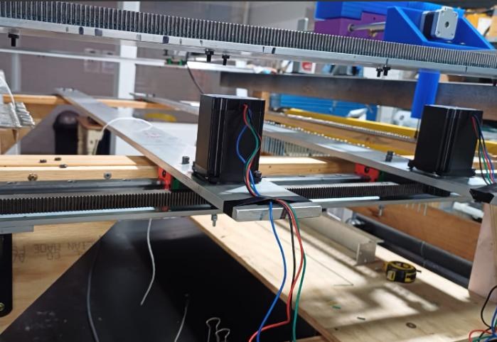
The previous CAD model did not move because of improper mating, and its rails and linear bearings sat between the frame and the rack, which made it hard to build. I fixed the mating and moved the rails and the rack to the side of the frame, so the beams run smoothly in the model and can be fabricated.

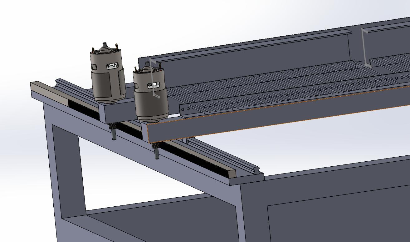
Before building, I compared four ways to move the beams: belt drive, lead screw with a stepper motor, linear actuators, and rack and pinion. Belts stretch, lead screws are slow and can bind, and actuators are expensive with short strokes. I chose rack and pinion for its range, cost and ease of servicing, and accepted that it needs careful alignment.
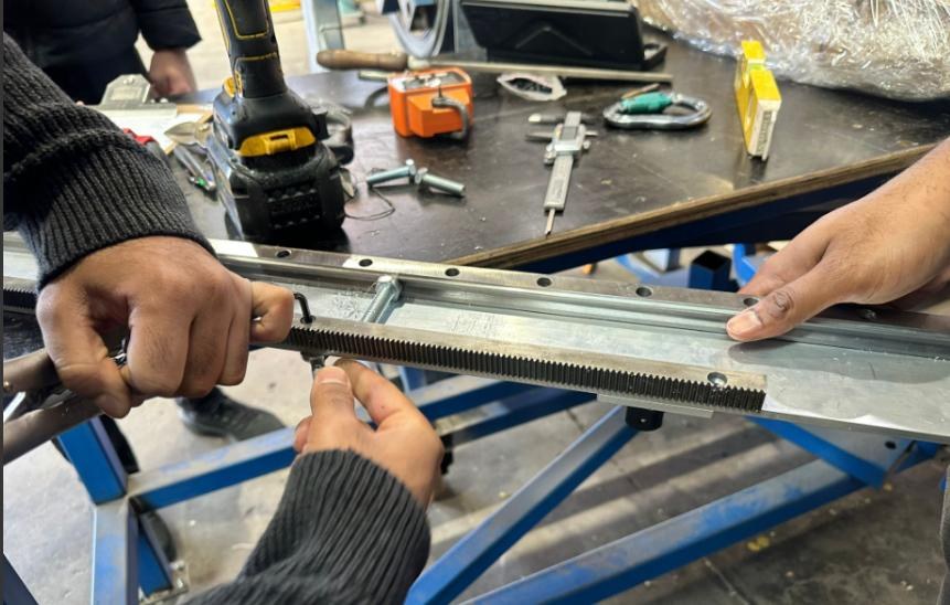
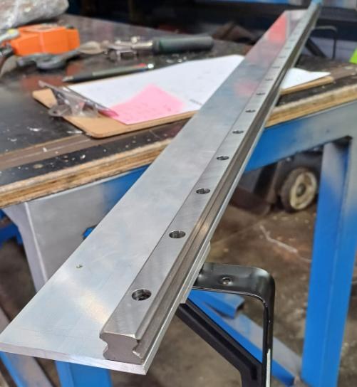
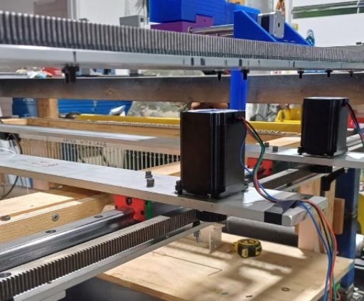
I then fabricated the platforms: aluminium bars on linear rails and bearings, with steel racks and spur gears driven by motors through shaft couplers. The motor shafts were too short to reach the rack, so I raised the rack on nuts and adjusted it until the beams ran smoothly.
Electronics and control
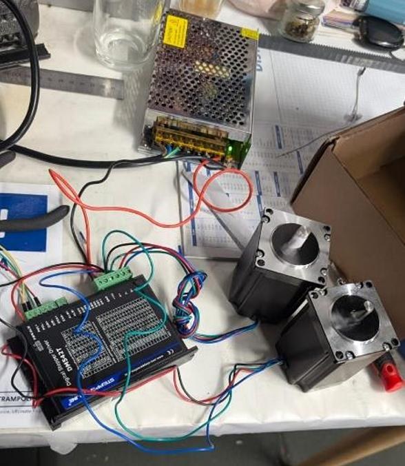
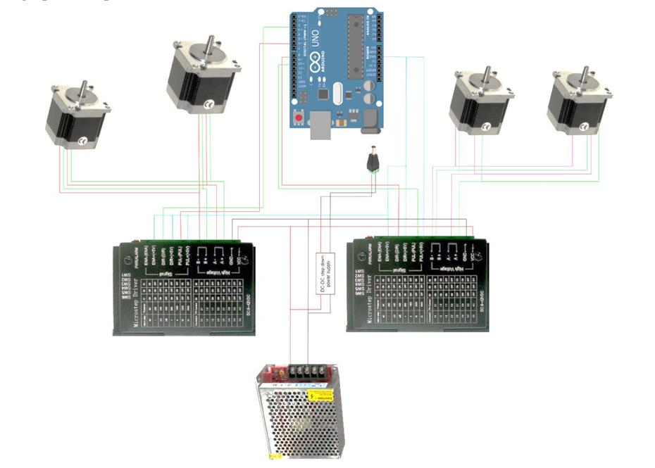
An Arduino Uno drives the stepper motors through two motor drivers on a 24 V supply. I assisted with the wiring and the code that moves the beams.
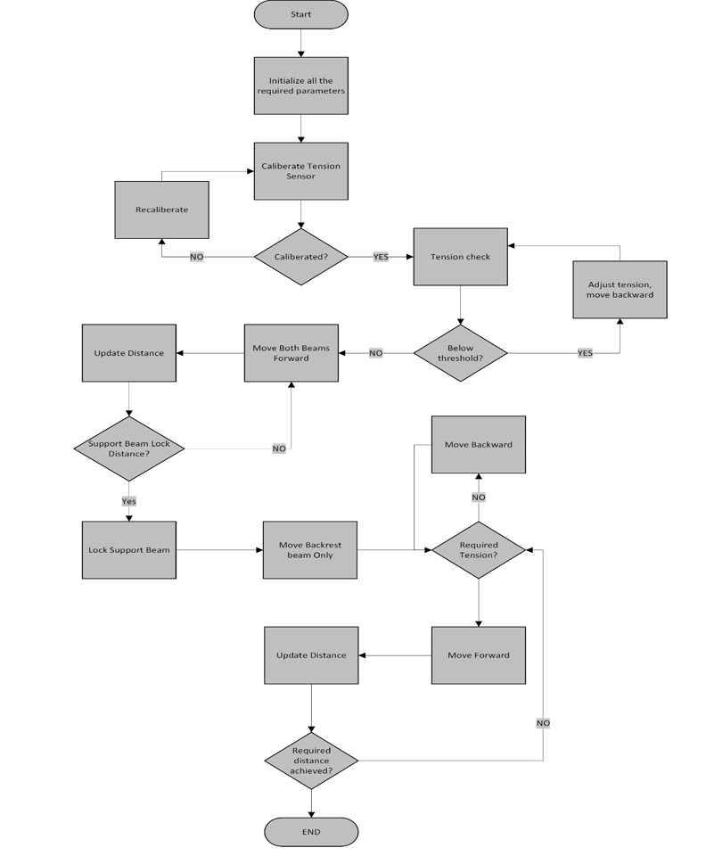
The flowchart shows the control logic planned for the full system: the beams move forward together while the tension is right, back off slightly if it drops, and the support beam locks at a set point while the warp beam carries on.
Results
- Both beams moved along their rails without jamming.
- The gears stayed in contact with the rack, with no skipped teeth.
- Vibration at high speed stayed within tolerance.
- Repeated moves showed no drift.
What I found
- A 2 mm error in rack height caused inconsistent mating and extra resistance.
- Nuts under the rack improved torque transfer and gear clearance.
- One degree of misalignment between motor, gear and rack caused jerky motion and wear.
- Moves that worked in CAD failed on the real frame because of dust, small frame misalignment and fasteners, so the design needs tolerance buffers.
Next
The next stage is to fit the strain gauges to the moving beam and recalibrate after each move, develop the closed-loop tension control, and integrate the system with the XY robot.